


Dudley J. Primeaux II, PCS, CCI
Primeaux Associates LLC, 161 Forest Drive, Elgin, TX 78621
primeauxassociates.com
Learning Objectives: Discuss the use of Thermal Imaging, or Infrared Thermography, techniques to evaluate the application of plural component, 100% solids thermoset coating systems. This technique can be used to provide guidance to consistent application film build in these coating systems.
Abstract: Thermal Imaging, or Infrared Thermography, is an evaluation technique that has been used in the general construction industry for many years. Often times this is used to evaluate the degree of heat loss in a structure for insulation purposes, or for detecting water leaks behind a closed wall area. Some recent cases have also shown this technique applicable for testing strength of concrete structures. Since high solids, plural component coatings system are based upon thermoset chemistry, they often exhibit exothermic characteristics during application. The use of thermal imaging techniques during application can provide for guidance in consistent application film thickness of these coating systems.
INTRODUCTION:
The use of Infrared Radiation (IR) Thermal Imaging is not something new to the industry, and has shown a wide variety of use in law enforcement, safety, military, medical, construction and sporting type application areas. IR Thermal Imaging (IR-TI) was first developed in the 1960’s with combined efforts of Texas Instrument, Hughes Aircraft and Honeywell, using heat given off by an object to help locate said object. 1-3 IR Thermal Imaging works based on emissivity, which is different than night vision, which amplifies, or intensifies, available light to locate and see objects. Night vision is characterized by the “green glow” in the object area. This is shown in Figure 1.
In firefighting applications, IR-TI can provide critical information to size up a fire incident, track fire growth, and locate victims, other first responders, and egress routes. Over the past several years, National Institute of Standards and Technology (NIST) Fire Research Division has been developing in the last several years, a suite of performance test methods for inclusion in a national consensus-based standard on thermal imaging cameras used by first responders. The performance metrics are related directly to the environment in which the imagers are used and tasks typically performed. 4 The same is true for law enforcement observation work.
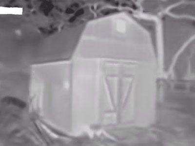
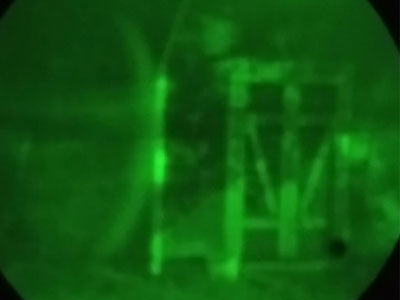
Figure 1: IR Thermal Image vs Night Vision Image, (l to r)
In a more focused use for purposes of this work, would be in the construction industry to monitor insulative properties of the structures, heat loss and possible water damage. The following Figure 2 is an IR-TI of a home during winter time to show potential heat loss areas. And while the FLIR label is noted on the Figures, this is company specific. However, the FLIR abbreviation stands for Forward-Looking IR.
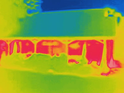
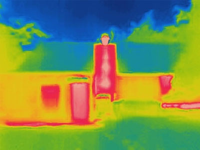
Figure 2: IR Thermal Images of a Home
From the Figures, the red to white color is the area of the most heat, with blue being the cooler spots. This is the IronBow Palette in IR-TI. As one can see, quite a bit of heat loss occurs at window and door areas.
In general construction work, IR-TI has recently shown promise for evaluation of concrete support pillars for strength. 5 This allows for detection of damage areas in the concrete pillars prior to concrete structural failure occurring.
Use in Coating Application:
Rather than a discussion on the history and use of IR-TI in insulative and general construction applications, will focus now on practical applications related to protective coating work. Recently, a technical paper was presented at the SSPC 2018 conference on the subject of determining Dry Film Thickness (DFT) of applied coating systems. 6 While this was not IR technology specific, the use of certain filters did provide for visual evaluation of applied DFT of the coatings. So let’s take this one step further.
What if IR Thermal Imaging could actually be used to evaluate and monitor the actual application of coatings? This is an interesting concept that has some practical potential. Since IR-TI works off heat emanated by the item observed, the applied coating system must be of thermoset technology. And for thermoset coatings, these typically are exothermic in nature, meaning heat is given off during the reaction and curing stage.
A common thermoset coating system used in protective coatings work are 2-part epoxy based materials. It is well known that 2-part epoxy systems are in fact exothermic. If the two components are mixed, then allowed to set in the container for an extended period of time, there will be excessive heat generated with melting of the container as that container is made of plastic. Most all have performed this activity at one time or another in coatings work.
The following Figure 3 is an IR-TI of spray application of a 2-part epoxy system. The video of this used in the presentation will actually show this in more detail. It can be seen that the spray is hotter (yellow to red color) than the surrounding area (blue to green color), but rapidly cools to the substrate temperature.
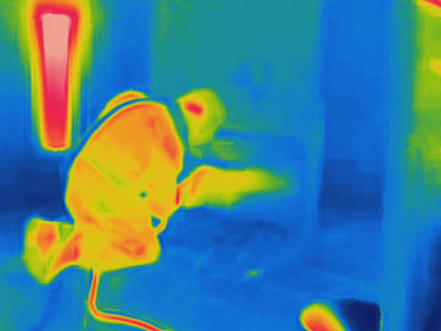
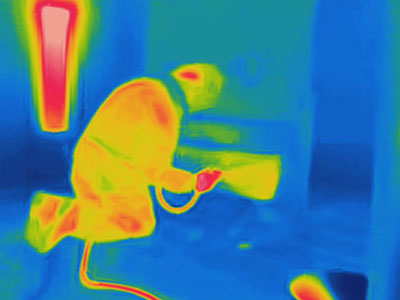
Figure 3: IR-TI of 2-Part Spray Applied Epoxy Coating
Since the applied epoxy is cooling rapidly upon application, the mass effect, the use of IR-TI may not be practical for real time in this case. Unless of course the 2-part epoxy is applied at significantly higher Wet Film Thickness (WFT) to achieve that mass effect and subsequent exotherm build. But then application has typically exceeded the required WFT / DFT, and significant sagging of the applied coating will result. And due to reaction rate of these systems, more conventional WFT testing is used during application.
In order to demonstrate practical use of the IR-TI during coating application work, it would be best if the applied thermoset coating system would be conducive to thick-film application with a fast reactivity and significant exotherm. The type of coating systems that fall into this category are the fast set, plural component polyurea and polyurea/polyurethane hybrid systems. 7 While these system are processed under highly heated conditions, exotherm values can be significantly high during application, and in many cases exceeding 200ºF (93ºC).
An example to illustrate the use of the IR-TI in a polyurea coating application, a project where an aromatic, fast set polyurea system was being applied to formed substrates for purposes of protection in vehicle dunnage applications. These formed substrates are used to support various automotive parts during shipment. The substrate itself is harsh on the parts, so a protective layer if polyurea is applied to cushion and protect the part from damage during transport.
In Figure 4, a picture of the coated part is shown. Normal visual inspection shows the applied polyurea system to be uniform in application, aesthetically pleasing. WFT measurements were not possible during the actual application as the gel time of this polyurea system was about 3 – 4 seconds. Recall that gel time for the systems is the time it takes to go from the liquid, fluid state, to a solid membrane. Also noted is the temperature of the applied coating within 2 minutes of application when this picture was taken. Spray application was performed at about 150ºF (65ºC), so there is cooling after application.
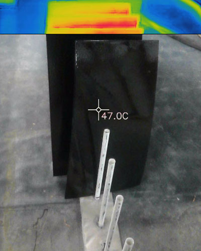
Figure 4: Application of Fast Set Polyurea to Dunnage Pieces
But when the same coated dunnage pieces are evaluated using IR-TI, a different picture observation can be noted. In Figure 5 both a white-heat output is used as well as the typical ironbow color IR-TI palettes. You can easily see that there are some lines of delineation on the panel, signifying heat emissivity variability in the applied coating system. This can be directly related to variable applied film thickness of the fast-set, thermoset coating technology.

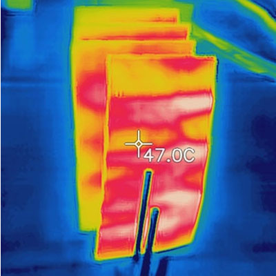
Figure 5: IR-TI of Application of Fast Set Polyurea to Dunnage Pieces
For these dunnage pieces, it was specified that 20 mils (0.5 mm) of the polyurea system was to be applied. In this case, the applicator used a single pass, one-coat technique, which is not necessarily bad practice for paints & coatings in thin-film application. From visual inspection, the applied thickness appeared to be uniform (from Figure 4), and the correct amount of material had been used per the surface area coated. But when DFT measurements were made, the following Figure 6 provides for values recorded. 8
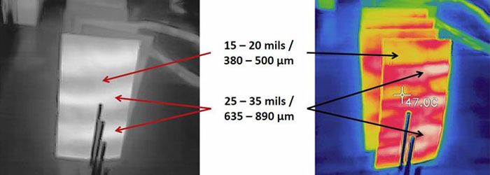
Figure 6: Thickness Evaluations, Fast Set Polyurea to Dunnage Pieces
Again, the thickness variability was due to application technique, and the not the material being used, in this case a fast-set polyurea system. An even though the thickness averaged out over the panel surface, the thinner areas could lead to poor performance and part failure. Hence application training and following industry standards of application are important. 9
Application of these type high-solids coating system should be in a multi-coat, criss-cross pattern. Spray pattern shall overlap at least 50%, and not match “edge-to-edge” of the spray pattern. This is known standard industry spray technique. And while the “W-technique” of application may be employed in roller application of paints & coatings, this is not good practice for spray applied coating systems. Figure 7 shows IR-TI of both “good” and “improper” spray technique. Visually, the surface of the applied coating was acceptable, but thickness uniformity was not consistent in the improper, W-pattern.
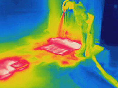
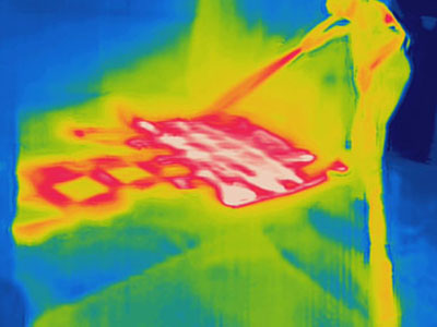
Figure 7: IR-TI of Good and Bad Spray technique, (l to r)
One of the more common applications for polyurea and polyurea/polyurethane hybrid spray coating systems is application over a geotextile fabric, primarily used in secondary containment application areas. Direct, simple non-destructive DFT testing is not as easy as if the coating were applied to a solid substrate and meeting required DFT conformance.10, 11 It has been shown that Ultrasonic DFT testing can be performed, but applicators should be versed in the use of this evaluation technique. 12
IR-TI can be used to monitor application consistency, rather than relying on just visual observation. To illustrate this, many uses of the polyurea / geotextile are in the form of in-house factory applied polyurea to the geotextile. This helps insure consistency and quality in the produced composite panels. The following Figure 8 and Figure 9 illustrate this work.
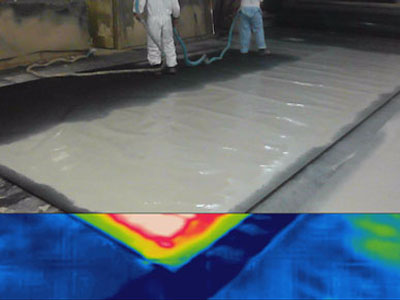
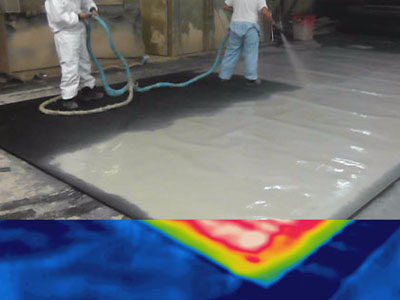
Figure 8: Visual Photograph of Polyurea / Geotextile Panel Production
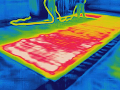
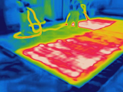
Figure 9: IR-TI of Same Polyurea / Geotextile Panel Production
When referring to the visual images, Figure 9, the application of the polyurea systems appears normal. The slight wrinkling of the fabric can be a common occurrence in this type work, and will depend upon the type of fabric used. When viewing the IR-TI in Figure 9, overall the thermal signature seems consistent and uniform. The slight wrinkling does have an effect on heat reflectance, which should be accounted for especially in outdoor evaluation work.
An important aspect of the fast set, plural component polyurea systems is that high processing temperature is required to achieve proper mix and resulting polymer properties. 13 This heat also lowers the mix viscosity and allows the material to flow better on the substrate; i.e. proper substrate wet-out. If the proper temp is not achieved in application, problems may arise related to substrate adhesion or surface aesthetics of the applied polyurea coating system.
So once the coating system has been applied and cured, IR-TI can be used to evaluate the coated surface for voids or blistering of the coating from the substrate. This is shown in Figure 10. Blister area is shown by the light blue color above and to the left of the window area.
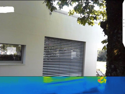
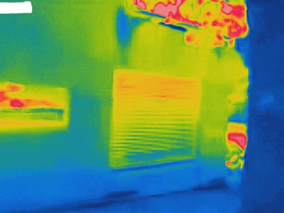
Figure 10: Blister Detection in Applied Coating using IR-TI
Notation:
The IR-TI pictures shown in this publication are a good illustration of what is possible with thermal imaging and coating application. However, video footage will be used in the actual presentation to better illustrate the point.
CONCLUSION:
The use of IR Thermal Imaging allows one to “see” what the human eye cannot see. In coating application, what may appear by visual observation to be uniform and consistent, may be plagued with defects and inconsistencies. Once fast-set, plural component coatings are applied and allowed to set and cure, DFT measurements can be taken, and may require repair to certain areas. This would be another step in the process.
And while there can be correlation to applied DFT, this is a better tool at present to monitor application technique, but not replace actual DFT measurements. This can also be used, in video capture, as a teaching and training tool for proper application techniques to help insure consistent application DFT of fast set, plural component coating systems. While this is not absolute, it is a start to real-time monitoring of application, with additional work in process.
References:
1 Thermal Imaging Guidebook for Industrial Applications, FLIR and Infrared Training Center (ITC), FLIR Systems AB, 2011.
2 Bagavathiappan, S., et. al., “Infrared Thermal Imaging for Detection of Peripheral Vascular Disorders,” Journal of Medical Physics, Volume 34(1), Jan – Mar 2009, pages 43 – 47.
3 Goswami, Priyanka, “Thermal Imaging and its Applications,” Technology, Linkedin® Slideshare, December 12, 2014, pages 1 – 31.
4 NFPA 1801, “Standard on Thermal Imagers for the Fire Service,” National Fire Protection Association, Quincy, Massachusetts, 2018.
5 DuBose, Ben, “Thermal Imaging Used for Nondestructive Testing of Concrete Pillars,” Material Performance, NACE International, April 29, 2018.
6 Yajko, Mike, et. Al., “Visual Determination of Film Thickness via Real-Time Enhanced Digital Imaging,” SSPC 2018, New Orleans Convention Center, New Orleans, Louisiana, January 14 – 18, 2018, pages 1 – 8.
7 SSPC-Paint 45, “Two-Component, Thick-Film Polyurea and Polyurea/Polyurethane Hybrid Coatings, Performance-Based,” Coating Standard No. 45, SSPC: The Society for Protective Coatings, Pittsburgh, PA, December 16, 2013.
8 ASTM D 7091 (latest version): “Standard Practice for Nondestructive Measurement of Dry Film Thickness of Nonmagnetic Coatings Applied to Ferrous Metals and Nonmagnetic, Nonconductive Coatings Applied to Non-Ferrous Metals,” ASTM International, West Conshohocken, PA.
9 SSPC-PA 14, “Application of Thick Film Polyurea and Polyurethane Coatings to Concrete and Steel Using Plural Component Equipment,” Coating Application Standard No. 14, SSPC: The Society for Protective Coatings, Pittsburgh, PA, September 25, 2012.
10 SSPC-PA 2, “Procedure for Determining Conformance to Dry Coating Thickness Requirements,” Coating Application Standard No. 2, SSPC: The Society for Protective Coatings, Pittsburgh, PA, May 1, 2012.
11 SSPC-PA 9, “Measurement of Dry Coating Thickness on Cementicious Substrates Using Ultrasonic Gages,” Paint Application Specification No. 9, SSPC: The Society for Protective Coatings, Pittsburgh, PA, February 1, 2008.
12 Primeaux II, D. J. and K. Bower, “Evaluation of Applied Film Thickness for Polyurea Thick-Film Elastomeric Coating / Lining Systems,” PACE 2009; The Power of Paint & Coatings, New Orleans Convention Center, New Orleans, LA, February 15 – 18, 2009.
13 Primeaux II, D. J., “Application of 100% Solids, Plural-Component Aliphatic Polyurea Spray Elastomer Systems,” SSPC 2000, Nashville, Tennessee, November 2000, pp. 95 – 102.